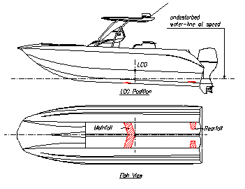
The abbreviation Hysucat stands for Hydrofoil-Supported-Catamaran which describes a hybrid type of Boat consisting of a planning type catamaran equipped with a hydrofoil system. A typical example is shown in the sketch of Figure 1.
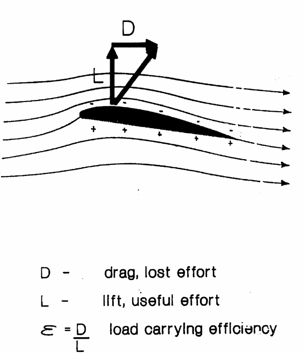
 A hydrofoil is a wing like structure which is installed under water and which is similar to an aircraft wing. It has a characteristic streamlined profile form which creates pressure differences on the upper and lower surfaces as schematically indicated in Figure 2 when it runs in a parallel flow. The pressure forces are negative on the top surface and positive on the lower foil surface. The summation of all the pressure elements on both surfaces results in a lift force L , (called �Lift�) vertical to the inflow and a dragforce D (called �Drag�), parallel to the inflow.
Such wings are used on aircraft wings, propeller blades, pump blades and fan and turbine blades and Hydrofoil Craft. In most technical applications the Lift L is a desired force (lifting-up force!) and the drag D is an undesirable force component opposite the flow vector because to overcome the resistance or drag force considerable energy has to be fed in by the engines and propellers which leads to fuel consumption with continuous costs.
The ratio of the drag D over the lift force L can therefore be considered as a kind of efficiency indicator:
e = D/L
and is known as the drag-lift-ratio.
 A planing craft running with high speed along the water surface maintains the attitude and trim due to dynamic uplifting forces, so called planing forces and therefore can be considered in a similar way as the above hydrofoil wing.
A comparison of the planing craft with the hydrofoil wing is schematically presented in Figure 3.
The drag-lift ratio of the boat is much higher than the one of the hydrofoil wing. Experience values show that the drag-lift-ratio of the foil is about 10 times smaller than the one of the boat.
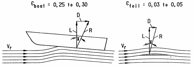
In short it means that the load carrying efficiency of the foil is much better than the one of the boat.
The basic principle of the Hysucat uses an efficient hydrofoil system in the tunnel between the two demi-hulls where it does not disturb view or operation of the craft. The hydrofoil system consists of a mainfoil in height of the keels and slightly forward of the centre of gravity of the craft and two smaller strut foils in the tunnel near the transom as indicated in Figure 1.
At speed the hydrofoils create dynamic lifting forces which keep the catamaran partly above the water level. This way the demi-hulls of the catamaran are moving less deeply submerged through the water which results in smaller buoyancy and lift forces which means that the hull resistance is smaller. As the efficiency of the hydrofoils is considerably better than the one of the hulls the total craft resistance of the Hysucat is much smaller than the one of the catamaran.
At speed the remaining hull parts in the water create sufficient transverse and course stability.
The arrangement of the foils is important to achieve sufficient longitudinal stability and requires that all the force components of hulls, mainfoil and trim foils are in balance around the centre of gravity at all speeds.
A special characteristic of the hydrofoil which is known as the foil-surface-effect and which means that the lift and drag reduce gradually when the foil approaches the water surface from beneath. This effect is used in the Hysucat for an automatic trim stabilisation.
|
For example, if the rearfoils approach the water level their lift reduces which means that the craft�s trim is enhanced which is desired as the planing hulls reduce the trim at high speeds. At very high speed the rearfoils may surface with their lift capability switched off.
In short the Hysucat maintains an efficient trim angle at all speeds which results in smaller wetted hull area with corresponding lower resistance.
To use the trim-controlling capability of the trim foils efficiently they have to be arranged somewhat higher on the inner tunnel wall near the transom as indicated in Figure 4 which means they run similar deeply submerged as the mainfoil.
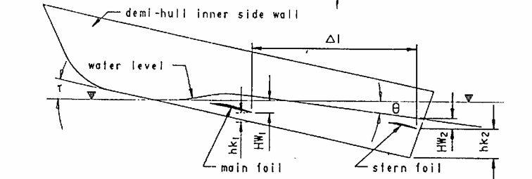 The mainfoil lift results in a down-wash with angle T and this also has to be considered for the rearfoil setting.
For the right arrangement with the corresponding foil submergences HW2 an automatic trim effect is created which gives the Hysucat a favourable and efficient craft attack angle in the whole speed range. Adjustable foils are not necessary.
The resistance of the Hysucat is much smaller than for the comparable catamaran and especially at high speeds. Around the year 1980 some tests on a Hysucat model were conducted in the towing tank at the University of Stelllenbosch, South Africa and the very first test showed a resistance reduction due to the foils of 40%. This unbelievable improvement led immediately to the creation of the Research Project �Hysucat� which now is active for more than 25 years and which has produced many more improvements by systematical optimisation.
As the resistance of the craft is directly proportional to the required propulsion power the Hysucat needs only smaller engines than the catamaran and is more economical in fuel consumption, even than usual deep-V-planing craft.
Further improvements of the Hysucat were observed on it�s sea-keeping and rough water behaviour.
The foil system gives a strong damping effect of the vertical and pitch motions which gives it a most friendly sea-keeping in rough water which does not exist on usual mono-hulls or catamarans.
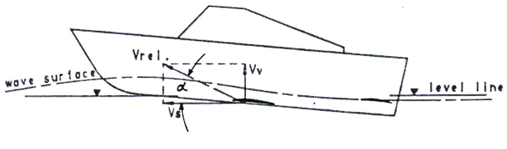 In Figure 5 the damping effect is demonstrated. If the Hysucat runs into a wave crest head-on the demi-hulls will be submerged deeper with a larger uplift force which pushes the forward part of the craft up.
This creates a change of the relative inflow angle towards the mainfoil with a smaller or even negative attack angle a which reduces the foil forces momentarily. In other words, by running into waves the hull forces are increased but the foil forces reduced.
When running through a wave trough similar force variations result, so that the total wave running behaviour gives much softer water in-and out motions. The extreme and hard pitch motions of fast planing craft in rough water are absent for the Hysucat.
Further details of the Hysucat development and applications can be traced on the FASTcc webpage and be studied in the given Research Reports and Publications- www.hydrofoildesign.com
In the development phase of the Hysucat a great number of towing tank model test series of applications were completed in order to optimize special craft to be built.
Later the Hysucat theory was developed which was applied for a Mathematical Hysucat Model in a computer program.
The finalized Hysucat product appears simple and is easily understood. The Hysucat design, however, is relatively complicated and is more similar to a Supersonic aircraft design.
Nowadays all Hysucats and foil system applications are optimised with aid of the Mathematical Hysucat Model by FASTcc and only in special cases towing tank model tests are applied (mainly for legal contract conditions!)
The Stealth � Hysucat series are built in South Africa and comprise Sport Boats, Yachts, Police Patrol Boats, Navy Offshore Craft of 5,3m to 22m.
The largest Hysucat built so far is the 45m E-Cat of Halter Marine, USA, and the largest design was for a 72m Buquebus car ferry with a displacement of 635 t. These larger semi-displacement type catamarans have a different foil system which is optimal for these craft at relatively lower Froude Numbers and is known as Hysuwac-System, see above webpage.
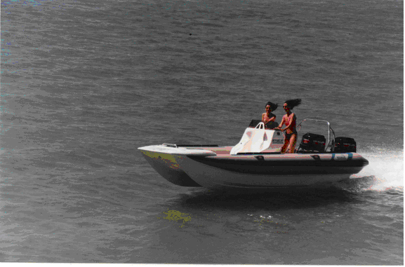
Figure 6 shows a photo of an early 6,5m Hysucat RIB at full speed easily handled by the two ladies. Of this Sport boat type over 250 units were build so far.
|